
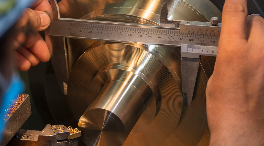
CNC metalworking and machining is a precision craft requiring precise quality control standards. When the time comes to assembling parts into a cohesive system, even a fraction of an inch can make the difference between a perfectly working system and a useless one. To ensure the quality of the final part, metalworkers have devised a system of quality control machining symbols known as geometric dimensioning and tolerancing (GD&T). In total, there are 14 foundational GD&T symbols—here’s what you need to know:
What are GD&T Machining Symbols?
For the uninitiated, GD&T is a system for defining and communicating engineering tolerances and relationships. It’s a collection of symbols found on engineering drawings representing different aspects of the final product. Rather than writing out the defined spec, each of the 14 machining symbols represents the specification. Geometric tolerances are applied to features by control frames. The most commonly used tolerance categories are form, orientation, and location; these 3 categories contain 10 of the 14 symbols.
Categories of GD&T Symbols
1. Form Tolerances
Form tolerances control the general “shape” of features and are often used as a refinement of size. There are four GD&T symbols within form tolerances:
Flatness:
It wouldn’t be surprising to know that flatness refers to how flat a surface is regardless of any other datum or feature. It’s useful if a feature is to be defined on a drawing which needs to be uniformly flat.

Straightness:
The standard form of straightness is a 2D tolerance that is used to ensure that a part is uniform across a surface or feature. Straightness can apply to a flat feature such as the surface of a block.

Cylindricity:
In simplest terms, cylindricity calls out how closely the part conforms to a true cylinder. In the sense of tolerancing, there are two concentric cylinders that run the entire length of the feature: one inner, one outer. As long as the entire length of the part fits between the two cylinders, it is within spec.

Circularity (Roundness):
Much like cylindricity, circularity describes how closely an object should fit into a true circle. Though, while cylindricity describes a part fitting into a 3D cylinder, circularity is only interested in the part fitting in a 2D circle.

2. Orientation Tolerances
Orientation tolerances control the “tilt” of the feature and are always associated with basic angle dimensions, often used as a refinement to location. When applied to surfaces, orientation tolerances also control form. There are three symbols that fit into orientation tolerances; they are:
Perpendicularity:
Perpendicularity requires the referenced surface or the line to be perpendicular (or 90°) from the datum surface or line.

Parallelism:
Parallelism, unsurprisingly, describes a parallel orientation of one referenced feature to a datum surface or line.

Angularity:
If parallelism describes how two parts would align with each other and perpendicularity describes how the parts should meet at a 90° corner, angularity is the symbol which describes a specific orientation of one feature another at a referenced angle.

3. Location Tolerances
Location tolerances control location and are always associated with basic linear dimensions. Position locates and orients the median plane or axis of features of size. Profile locates features surfaces. Profile is the most powerful of these, since it also touches on orientation and form tolerances. There are three symbols under location tolerances, which are:
Position:
Position (or true position) is one of the most useful, but also one of the most complex of all the GD&T machining symbols. The two methods for using position will often use either the “regardless of feature size” or under a material condition. Position is always used with a feature of size.

Profile of a Surface:
Profile of a surface describes a 3D tolerance zone around a surface—usually a curve or shape. If defined on a curved surface, the entire surface where the radius is must measure within the tolerance zone.

Profile of a Line:
Profile of a line describes a tolerance zone around any line in any feature, usually of a curved shape. Profile of a line is a 2D tolerance range that can be applied to any linear tolerance. If it’s called out on a surface—the radius of the part, for example—profile of a line specifies how much a cross-section could vary from a true curved radius.

Precision Machining and Precision Delivery from Winndeavor
Metalworking, by its nature, requires utmost precision. Parts must be able to fit together in the space allowed, which is why the design of any manufacturing process is just as important as what happens in our lathes and mills while we’re shaping the piece of stock. GD&T is a universally-understood language, which helps save time and money, while still delivering the high quality needed.
Winndeavor is committed to precision. You can rely on us to deliver precision parts when you need them. To find out more about how we do it, visit our website and contact us.


